Painting an AussieSpeed GT Shaker
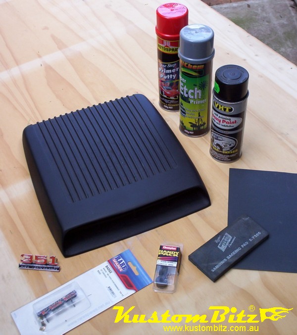
This little project of preparing and painting a GT Shaker is to show you how you can do it yourself at home and get that factory muscle car look with some simple tools and some cans of spray paint from any speed shop or auto store.
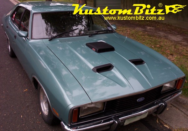
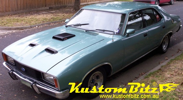
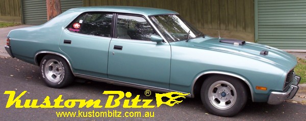
This shaker is destined to go on my own car, a 1978 Ford XC Fairmont GXL, however this example of how to fit a shaker could apply to a Mustang, Torino, Ranchero, Falcon XM, XP, XR, XT, XY, XW, XA, XB, XC, XD, XF, even an F100 or dare I say it a Chev, Holden or Valiant, the list is endless. Of course you could get it painted at your panel shop and you could also not bother to go to this trouble and may just want to spray some black over it and bolt it on, it depends on how fussy you are.
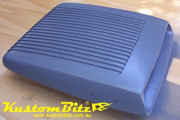
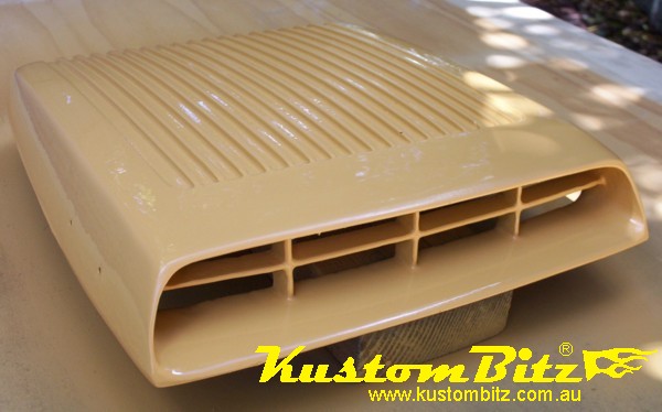
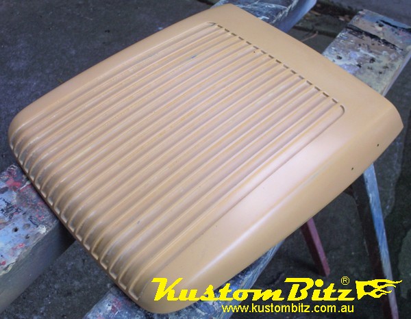
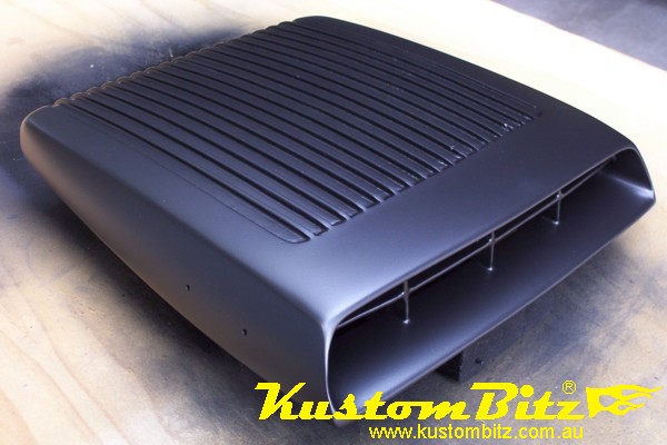
The AussieSpeed GT Shaker is a good copy of the original ford units made back in the 60s that came out on the famous Australian muscle car XY Ford GT Falcon. The USA Fords had this style of shaker fitted to the Mustangs, Torinos and other Ford performance vehicles.
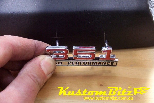
It is sand cast in Aluminium [Aluminum for our USA friends] and is supplied polished or in etch primer black. We are going to prepare a black one for paint and before painting I am going to drill it so we can fit a 351 high performance badge to each side.
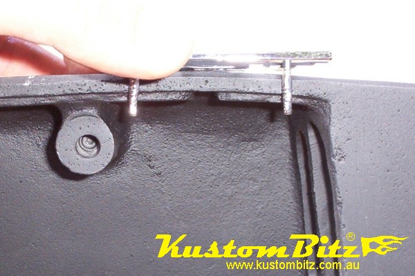
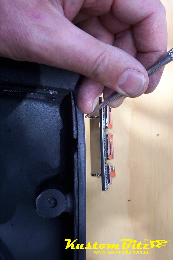
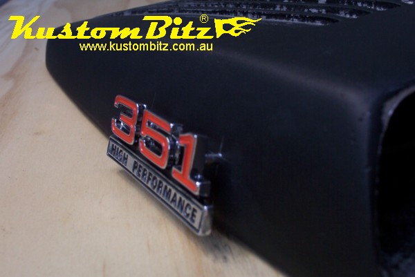
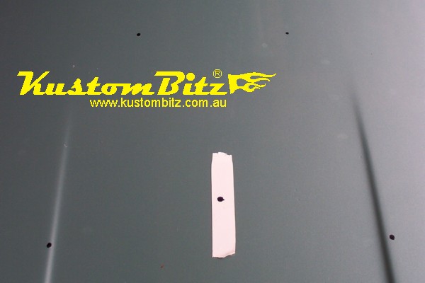
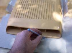
You can see here that we have to be careful to position the badge so we do not foul the attachment boss on the back side of the shaker.
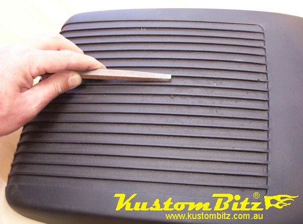
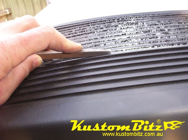
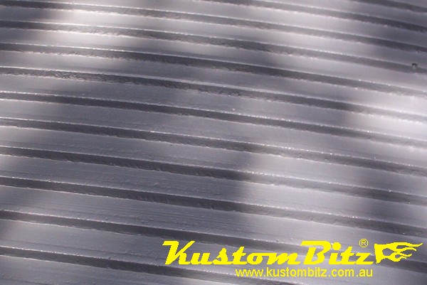
One of the remnants of the sand casting is that between the fins on the top of the shaker it is still a bit rough and it has some sharp high spots. Now not many of you will notice them but me being a bit anal and a fussy bugger I have decided to knock them down with a file so that it will look better and be easier to clean.
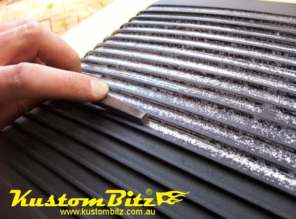
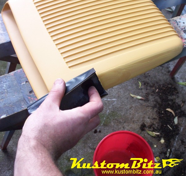
I need a square file that can fit between fins as shown here. I move the file in long steady strokes along between the fins until all the high spots are knocked down and the deep corners of the fins are squared up. As I go I can see the high spots being filed away and I can use my fingers to feel how smooth it is.
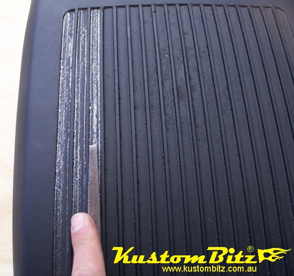
This photo shows you that I am only using this part of the file, the very end last inch or so and I make sure it is flat in the fin and at a slight angle, so that I end up with a gentle scraper action and not leaving big scores in the alloy.
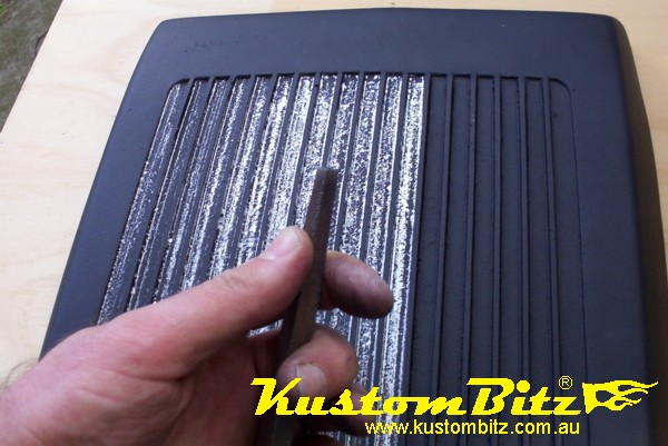
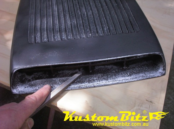
As I was going I decided that I would knock down the areas around the opening at the front too……I did say I was a fussy bugger didn’t I? 
As I worked on the shaker I also noticed that the top front edge needed a bit of rework to gently re-shape the top lip and centre it up. The good thing with alloy is that it is easy to work with and you can achieve good results with simple tools.
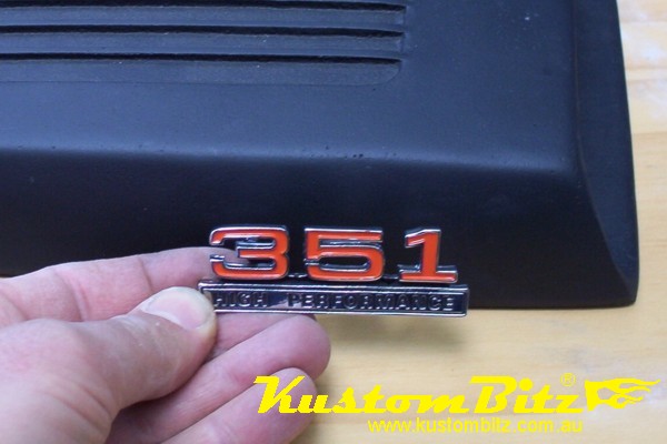
Ok let’s position the 351 badge. This 351 High Performance badge came out on XW & XY Ford GT Falcons and this one here is a reproduction made by Rare Spares with a part number B2031. There are two sizes made by Rare Spares and this one is the smaller size that is usually intended to be fitted fitted to the glove box lid or glove compartment lid on the dashboard.
An alternative to this badge if you were fitting the shaker to a Windsor powered Mustang, XR or XT falcon would be to use the 230hp high performance badge. Late model fords like the EB XR8 or the BA Falcons you could use the more modern looking XR8 badge on the side. I have also seen reproduction Cobra Jet badges that were originally fitted to the shakers on the CJ 428 big block Mustang, they look real good.
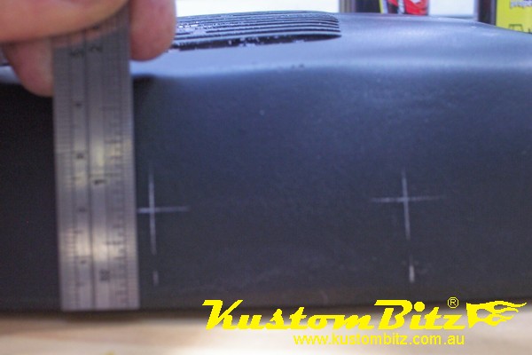
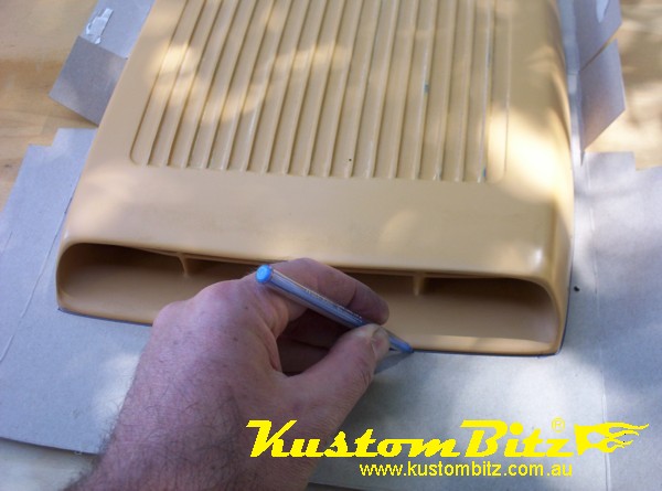
Scribe some lines using the badge itself as the guide. I decided I wanted the badge to sit low on the shaker and parallel to the bottom edge. I marked for drilling the holes at ¾ of an inch above the bottom edge[20mm]. I wanted it to sit low so that I don’t knock it when washing the car and secondly the centre of my XC bonnet is raised so I think it will work well.
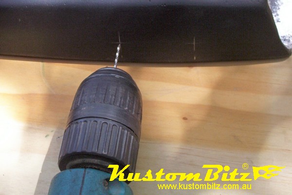
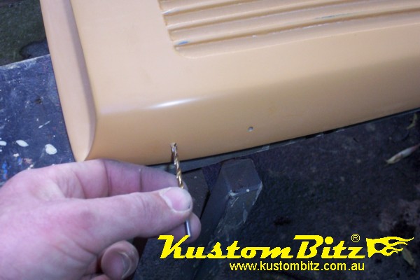
Use a small drill bit for your pilot holes and check them once drilled against the badge. Then if they look right, open them up with a drill bit that matches the pin diameter on the badge. In my case this was a 3.2mm drill bit.
Test that the badge will line up with the holes, but do not push it all the way on just yet, there is a good chance you will brake it trying to get it off again if you push it all the way on now. Remember the badge is only diecast and quite thin so be gentle. Now by drilling close tollerance holes you will find that the badge will need some force to push it all the way on, this is part of our cunning plan because this will help it stay where it should and not fall off.
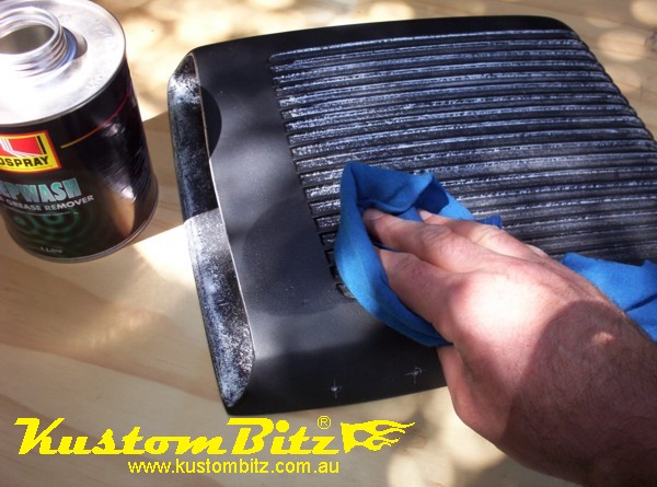
Now we need to remove all filings, dust and grease with some prep wash grease remover.
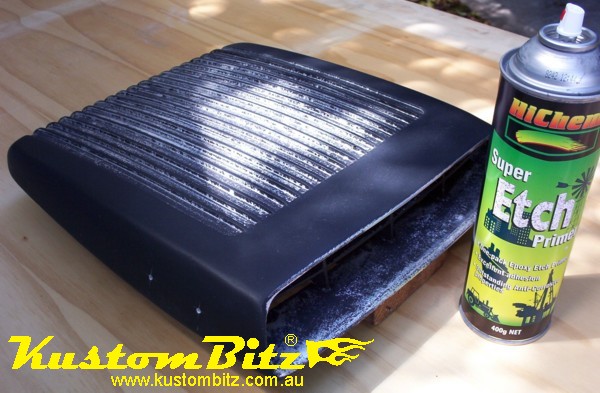
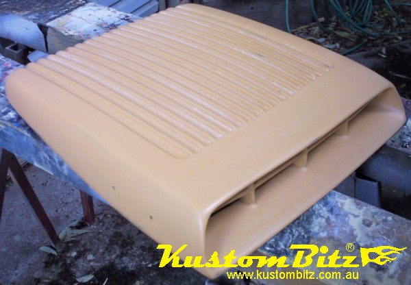
First I am going to paint the shaker with an etch primer again because I filed allot of the old etch primer off. I am meticulous [anal] about making sure the paint is going to stick which is why I am using the etch primer first. Leave it for an hour or so to dry.
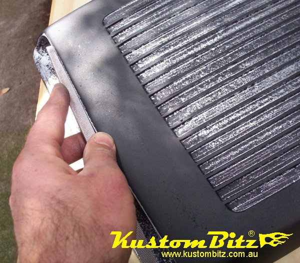
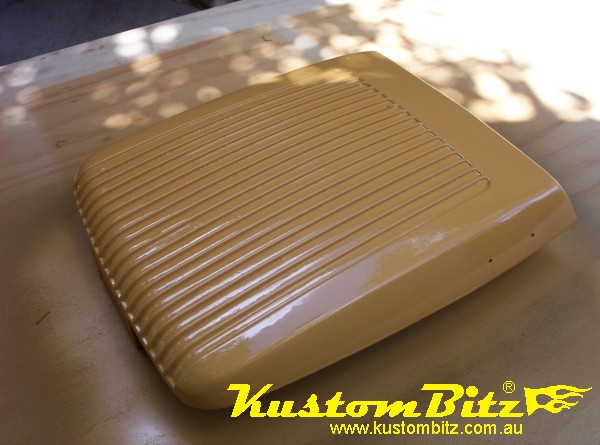
You can see here that the top of the shaker between the fins is already looking pretty good.
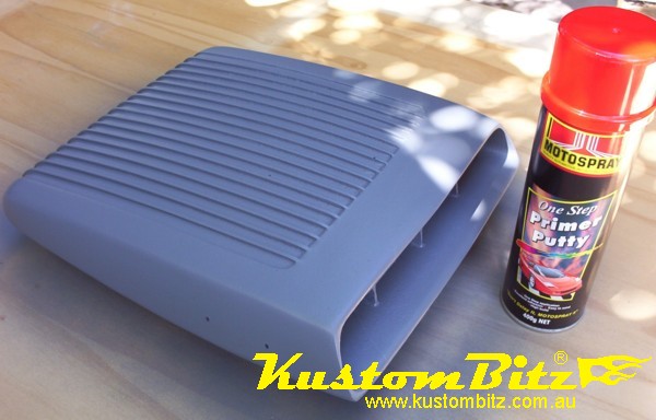
Second I am applying this primer putty which is a high build so you can put it on thick and fill all those little pin head dimples that is typical of a sand casting. I put the first couple of coats on just to cover it all up, then once this has stuck I lay it on thick in the areas I need it until it is almost dripping…………notice I said almost…….. if it runs it does not matter too much you just have more sanding to do, however it also takes a lot longer for a big drip to dry all the way through before you can sand it. Basically I put the putty on thick so as to fill all the low spots, then the sanding process takes off most of the paint I just put on and levels out the surface.
Now you need to leave for anywhere between 3 and 5 hours on a hot day to let it dry and harden right up so you can sand it.
Our GT Shaker has a lot of curves and edges so I decided to use a 1000 grit wet and dry sand paper to water sand the primer putty back to a nice flat finish. This grit will mean that if I am careful I will only have to sand it this once and not recoat to cover scratches made if I had used a more course sand paper.
The area in between the fins I did not spend too much time on, I just used the paper on the end of my finger with plenty of water just to knock down overspray and high spots. However for best results I use a soft flexible sanding block to do all the flat curved edges so I get a good flat surface for top coat.
There is a bit of an art to sanding, but above all you have to continually look closely at your progress by washing off the dirty water. When you are working a flat area, stay away from the edges. For example don’t apply pressure on the block so that it sands the edges until you have knocked down the flat areas, this is because the edges sand really quick. You can shape edges easily at the end once the bigger expanses are done.
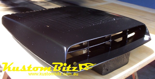
Here is the shaker after sanding, you can already see it is refecting off the flat surfaces even though they are sanded and dull, this is going to look pretty good. Notice how I have not sanded through on all the edges, if you have then you will need to apply some etch primer to the bare sections of alloy and leave to dry before applying top coat.
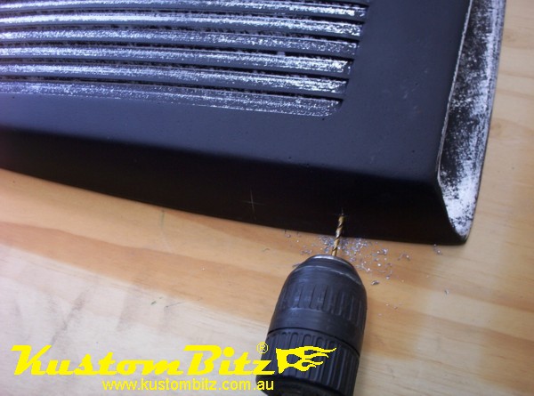
One little but important attention to detail is to just run the drill bit through with your fingers to take out the spray putty from your badge holes. This will stop the paint chipping off when you go to fit your badge later on.
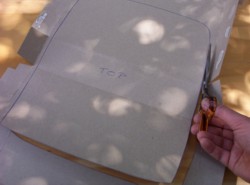
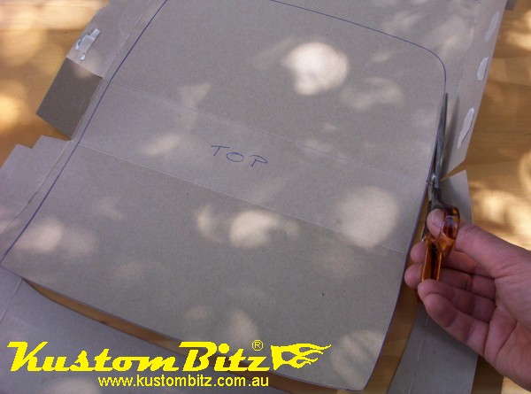
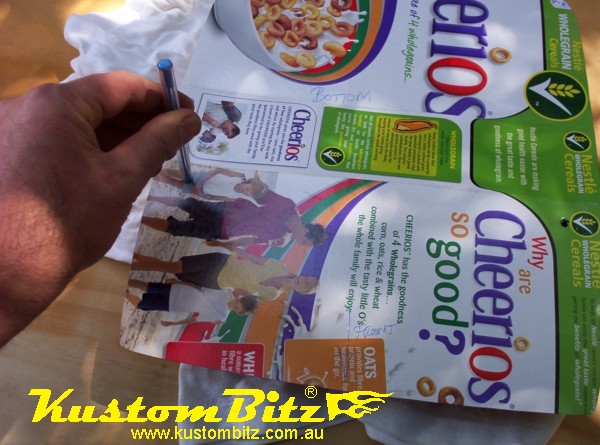
So I don’t scratch the shaker when it is finished I decided to make a cardboard template now before I put the top coat on, so I can plan out where to drill my holes in the bonnet. Keeping the theme of using what is available about the house I use the kid’s cereal packet to cut up as the template. Be sure to be accurate when punching the holes in the card for the shaker’s fixings.
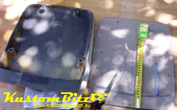
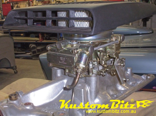
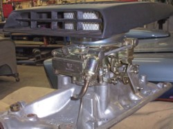
I have marked the template with my centre position that I want. In this instance I have marked this position 170mm back from the front edge. This would allow me to run a small 6 inch air cleaner up into the shaker if I were to run a high rise inlet manifold like for example the TFC for the Ford Cleveland which places the carb right up close to the bonnet. The following photo shows a mocked up example of a 600cfm Holley carb on a Holley Street Dominator single plane manifold with a 6 inch element and base. It gives you a general idea of how this could work.
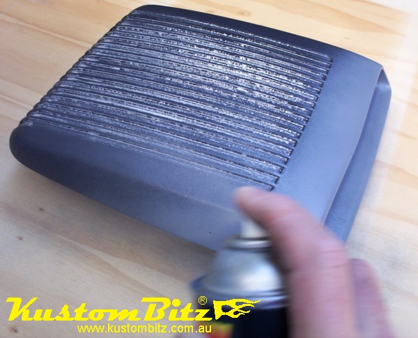
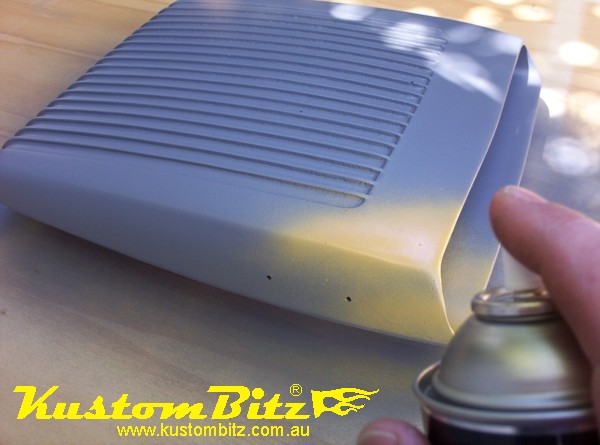
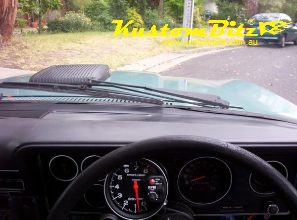
Now we need to prep wash the shaker and remove all dirt and grease before final top coat of black. I am using a satin black to match the colour I originally painted the scoops in my bonnet. I like the satin because it is subtle and dirt washes off it more easily than a matt finish. Of course gloss black would look good too, seeing that we have gone to all this trouble to prepare it. Make sure you paint the back first to get rid of all the primer overspray.
I am hoping that I am not going to colour sand, so I only need enough black paint to cover it to get a good even colour and finish. Remember too much paint can easily chip if it is knocked so we do not need to lay it on too thick.
Hoping not to colour sand and actually not doing it was all averted when the wind sprung up and blew debris all over my tacky paint……so much for doing it at home. Oh well it is character building I am told ...... any one got a spray booth?
Once I colour sanded it I double checked the nostrils in the XC ford bonnet and I had actually painted them matt black which I decided would work better on the GT Shaker too so I changed my mind and the final top coat ended up matt black. It looks much tougher and I got a pretty good finish on it now.
Leave it to dry for a good 8 hours before fitting the badges. The paint may be dry but it will be quite soft for some hours and we do not want to undo all the good preparation work we have done.
To fit the GT Shaker to the XC falcon bonnet I am going to first work out where the centre of the carburettor is, because that will determine where the shaker should bolt to the bonnet.
In this instance I am only bolting the shaker to the top of the bonnet for looks more than anything……… a poser ……… I am not cutting a hole below the shaker, however I will pay close attention to its location should I decide to fit a high rise manifold and I need to cut a hole at a later date.
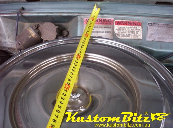
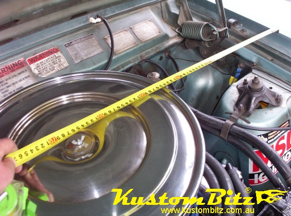
With the bonnet up measure from below the windscreen to get the centre position of the carb, now measure also from the mud guard edge. Note that some engines do not sit in the middle of the engine bay, so pay attention.
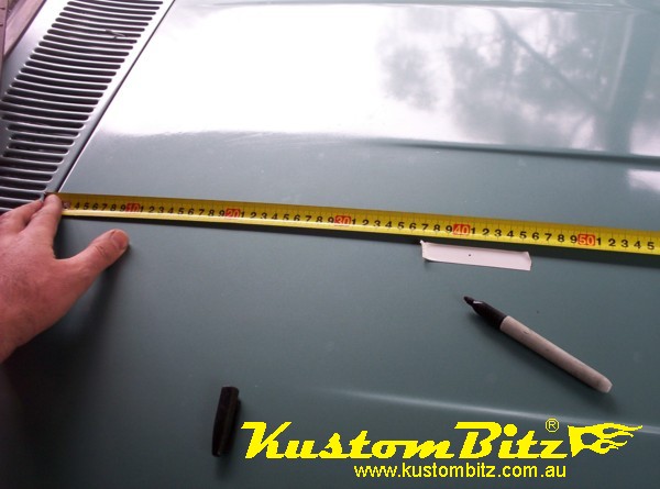
Now close the bonnet and use some masking or electrical tape on the top side of the bonnet to mark the centre of the carb. I like to use electrical tape because masking tape can lift paint off your bonnet if the paint is not too flash.
Now place the cardboard template you made earlier on the bonnet with the centre hole lined up with the mark for the centre of the carburettor. Double check that your template is squared up to the bonnet edges and if you are happy with its position you can mark out the holes for drilling.
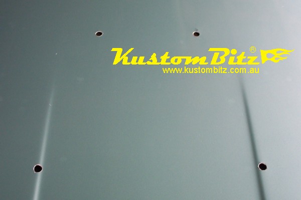
Double check all measurements and drill holes.
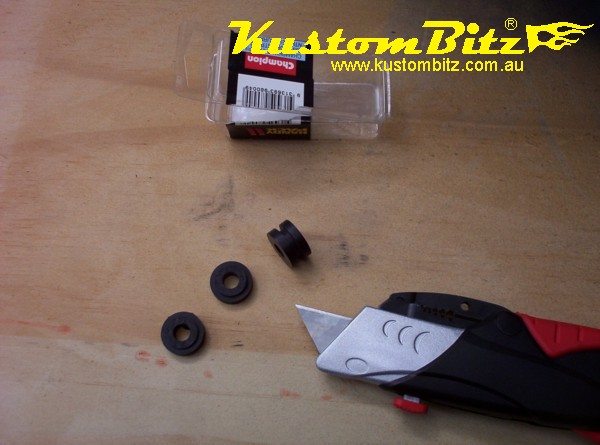
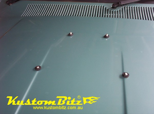
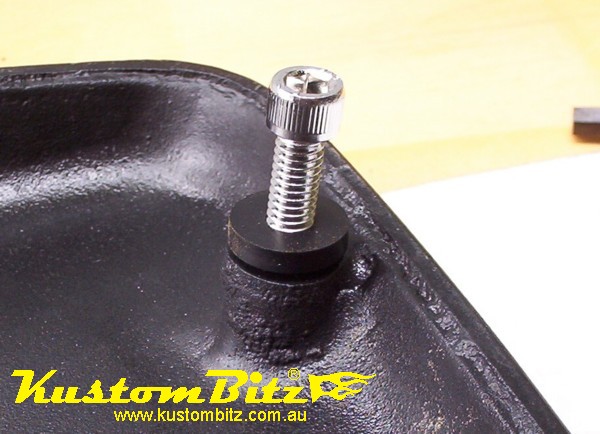
The XC bonnet is curved and has ridges that do not allow the shaker to sit perfect along the bonnet. I have decided to cut some 5/16 wiring grommets in half and use them between the shaker and the bonnet surface to clamp between and tighten up on. This will allow a small gap so that the shaker does not actually touch the bonnet at its edges. These grommets will help when installing the shaker because they hold the bolts in place.
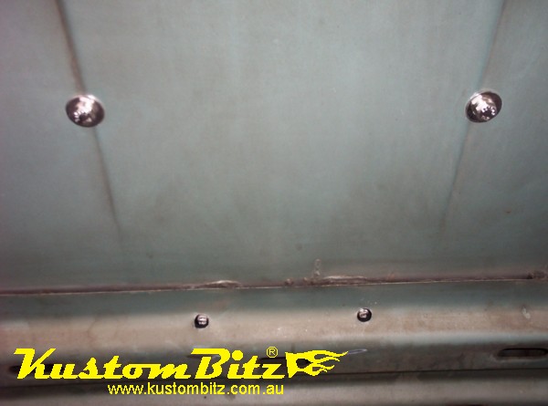
For bolts I have used our Kustom Bits budget range stainless steel 5/16 mud guard bolts and washers to attach the shaker. The back holes line up with the second skin of the bonnet frame so I drilled 1/2 inch holes on the underside only so that it would allow socket caps to go up through it.
.......... and yes my Ford is quite dirty under the bonnet ....... remember this is not a show car it is my daily hack, that I just like mucking around with, keeping it fun and low budget.
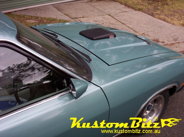
So there you have it all done, looks pretty cool I think. The only thing I would do a little different is install the 351 high perfromance badge 1/4 inch [10mm] higher.
Here are some more photos of the shaker fitted to the XC from a few different angles so you can see how cool it looks. 
Now one would ever know you are covering up the top of a small 6 inch air cleaner or a velocity stack that is just poking through the bonnet. It is a steet legal bonnet scoop, you have a Ford factory performace look and best of all it is not a flimsay fibreglass scoop, the GT shaker is solid alloy.
If you had something taller poking through the bonnet you could be clever and raise or alter the sheet metal profile of the bonnet to gain extra height and then sit the shaker on top of that. If executed well it could still look factory.